
This scooter was built on the small budget of a grad student with a family. The total cost was under $300, over an order of magnitude cheaper than the real Segway.
Update – 25 Sep 2013
I did some work over the last year for a power-tool company who contacted me about building a balancing scooter from their tool parts. Their shop handled the mechanical construction, and I spec’d the powertrain and electronics, made a new PCB to interface with the (non-Nintendo) sensors and more appropriate motor drivers, and tuned the system. I don’t have permission to post photos or videos of it right now, unfortunately.
(Getting paid in power tools? Awesome.)
Update – 26 Mar 2012
The Segfault was featured on Hack a Day last week!
Update – 17 Mar 2012
I recently added TVS diodes to the motor drivers and put the batteries in series for 24 V. The speed has increased as expected, though I haven’t been brave enough to try it full out yet. The balance also seems a bit smoother. The one problem is that one of the motors has been sparking and putting out puffs of smoke. I think some oil may have gotten on the commutator and that the brushes may be bad, so I’m going to do a teardown of the motor sometime soon and try to resolve the issues.
I decided to go ahead and post the code in case anyone wants to reference it. I’m sure it’s ugly code, but it works.
Control system
The Segfault runs off of a Cypress CY8C29466 Programmable System-on-Chip controller. The loop rate is about 100 Hz. During each loop, either the accelerometer or the gyroscope is read and the motor duty cycle is updated. I tried to write the code from scratch as much as possible, but I have to give credit to Trevor Blackwell and the MIT FIRST group, whose code I referenced. You can view the code here. (Disclaimer: I make no claims to be a good coder, and I bear no responsibility if you use any of my code for your own project and hurt yourself :).)
Sensors
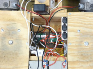
The system uses Wii hardware for it’s balance sensors and steering. I used these because they’re cheap—cheaper than just the sensor chips alone were—and they do the analog-to-digital conversion on board. I removed the guts of a Wii Nunchuk from its case and installed them in a small box, which is mounted on the pivoting handlebar shaft. It’s the black box at the top of the picture below. Two of the built-in accelerometers (front-back and up-down) are used for balance, and the other (right-left) is used for steering. A Wii Motion Plus is mounted on the chassis, and one of its gyroscopes is used for balance. It’s the white module in the picture. Thanks to the folks at WiiBrew for posting information on how to retrieve the sensor data over I2C.
Motors and motor controllers
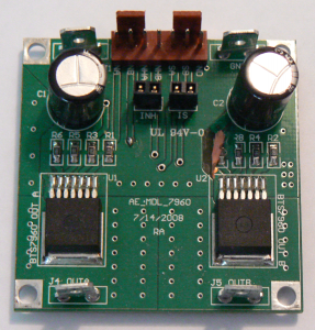
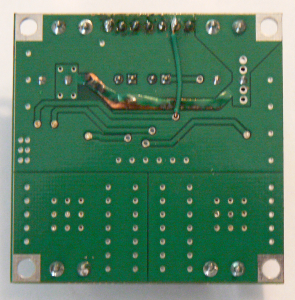
I’m using two motors from an Invacare electric wheelchair I found on Craigslist, along with the accompanying gearboxes, wheels, and tires. The two motor drivers are based on the Infineon BTN7970 half-bridge, which is rated to handle up to 70-A bursts and a continuous current of 40 A. The boards are Avayan Electronics’ MDL-7960, which are very similar to the Robot Power Simple-H board. They are the two green boards in the picture above. One difference from the Simple-H is that these boards don’t have transient-voltage-suppression (TVS) diodes. I found this out the hard way when, during one of my first tests, one of the boards blew out (see pictures below). I was running off of 24 V at the time, and I think the cause was a back-EMF spike that fried one of the half-bridges. I’ve since been running at 12 V, which reduces the top speed by quite a bit, but seems to have prevented more blown out controllers. I’ve been meaning to put in some TVS diodes for some time, but I haven’t gotten around to it yet. I found some heat sinks to put on the half-bridge chips and attached them using adhesive heat-conducting pad.
Batteries
I am using two 12-V 22-Ah AGM lead-acid batteries. They are currently connected in parallel to provide 12 V, but I plan to put them in series for 24 V once I get the TVS diodes put on the motor drivers.
Interface
There are three power switches for the system: one for the control circuitry and one for each motor driver. The h-bridges are enabled by holding down one of two dead-man switches on the handlebars. Another button puts the system in what I call “tow mode”, which drives the motors proportionally to the tilt without trying to balance the system. This allows me to move the system around quickly without riding it. Steering is done by tilting the handlebars from side to side.
Chassis and handlebars
The chassis is constructed of pine board, plywood, and a couple pieces of aluminum angle as reinforcement. The handlebars and handlebar shaft are made of PVC pipe. The pivot for the handlebars is made of pine board and PVC fittings.
Current problems
- It’s slow. Switching to 24 V once I get the TVS diodes installed should help a lot with this.
- It can’t handle big slopes for very long. This is due to the half-bridges overheating. I added heat sinks, which help some, but I’ll be adding cooling fans too.
- It tends to buck when new riders try it. I think this is due to the balance accelerometer being mounted on the handlebar shaft, which is somewhat loose. A better pivot for the handlebar should help to fix this. I may also need to do more tweaking of the feedback parameters.
Planned upgrades
- Install cooling fans for motor drivers.
Install TVS diodes and switch back to 24 V.- Install on-board battery charger.
- Replace wooden chassis with welded steel tubing and replace handlebars and handlebar pivot with something better.
- Tidy up the rat’s nest of wiring.